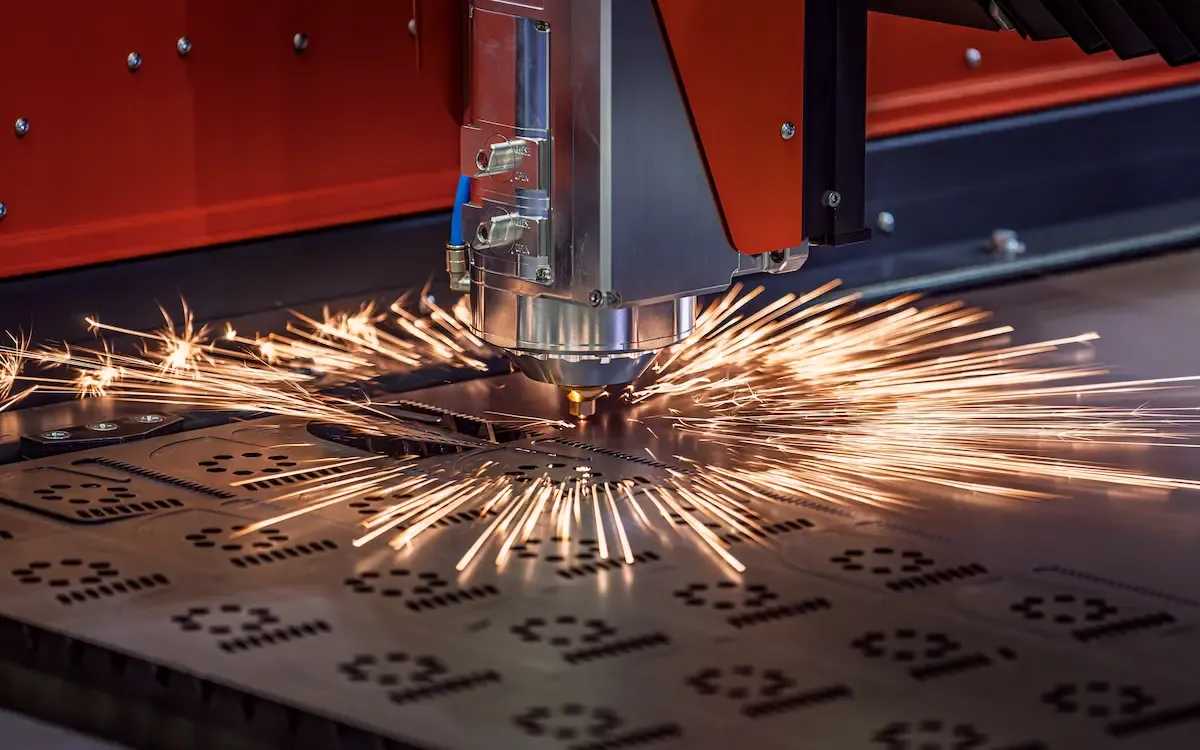
Laser drawings on sheet metal for custom productions
When it comes to laser drawings on sheet metal, anyone who runs a workshop or carpentry shop knows that the file is not just an attachment, but the element that decides the stability of the entire cycle: time, scrap, edge quality, and the ability to bend or weld smoothly. A poorly prepared drawing wastes minutes on each part, a well prepared drawing allows frictionless integration of laser cutting with bending, punching, and welding, especially when working on short runs or different components in the same day.
The real difficulty is not so much “cutting,” but ensuring that the part leaves the laser already prepared for further processing. A slightly wrong geometry in the bending area, a fillet that is too tight, a minimum distance not respected between two cuts may seem like insignificant details until you get to the press brake or welding bench. At that point you find that that detail costs more time than the whole cut put together.
Working from laser drawing in daily production
Regular laser users know that the CAD file is often the least controlled part of the entire process. There come drawings exported in a hurry, broken curves, overlaps not visible to the naked eye. The machine interprets them all, one by one, and each micro-segment is read as a separate command. This causes pauses, vibration, or heat buildup on small areas that can deform the sheet metal, especially on thinner thicknesses.
A clean pattern, on the other hand, allows for continuous work: the head advances without hesitation, the edge remains uniform, and no extra finishing passes are needed. The difference is most noticeable when the workpiece has many interiors or details close together. In these cases they become critical:
- Continuous contours with no “dead” spots;
- Fittings consistent with the thickness and minimum achievable radius;
- Absence of duplication or overlapping features;
- Reasoning about local deformability during shear.
These are aspects that take a few minutes in CAD but save hours in production, especially if the part must then be bent with precise references or assembled in a carpentry that requires consistency between multiple elements.
From CAD file to part ready for bending or welding
Preparation of the design for truly efficient cutting
A well-prepared design is not the one that is “beautiful,” but the one that reduces operational uncertainties. When nesting contains very small elements, narrow slots, or traces that change direction suddenly, heat input can build up in one spot and generate micro-shrinkage. It often happens with thin stainless or 2-3 mm aluminum: the edge looks clean but, at the bend, the sheet is already slightly deflected. Hence the need to check some basic conditions.
Before sending a drawing to the laser it always pays to check that the export has not introduced segments that are too short. Sometimes all it takes is two-tenths of a millimeter to force the head to a sudden stop that makes the heat input erratic. The same is true for theoretically perfect curves that, after export, turn out to be composed of thousands of micro-arcs. In these cases, the machine struggles to maintain a constant speed, creating an uneven edge that complicates subsequent robotic bending.
Choice of parameters according to alloy and thickness
Once the design is correct, actual performance depends mostly on how power, focus, and assist gas are set. Carbon steel is generally the most “tolerant” material, but just going up with thickness or inserting very close strokes is enough to notice color differences or small longitudinal deformations. On stainless, the use of nitrogen allows a clean surface to be maintained, while on aluminum, fire management becomes critical to prevent the sheet from losing rigidity in thin areas.
Most organized shops adopt a simple rule: define a parameter package by material/thickness and update it over time based on the most critical parts. This reduces testing and makes the behavior of the sheet metal in subsequent operations more predictable, especially when the part will need to be mated to a reduced tolerance or welded to an already calibrated structure.
Custom aluminum machining and heat management
Custom aluminum sheets are often the most delicate part of the job because the material reacts to heat very differently than steels. Aluminum heats up quickly, tends to expand in the heat-affected zone, and can lose stiffness if the pattern contains sections that are too close together. The main risk is localized deformation: a seemingly perfect cut may show a slight curvature that becomes evident only when the part is placed in the bending machine.
In these cases it is useful to rethink the design: increase the fillet radius, widen the minimum distances between two profiles, or avoid too fine details on thicknesses less than 2 mm. The sequence of machining also has a great impact. Cutting the most sensitive area first, then moving on to the more massive area, helps distribute heat better and reduces overall deformation. When the part will be destined for welding, edge accuracy becomes even more important, because unanticipated shrinkage can compromise component alignment or bring out internal stresses after cooling.
Technical table for consistent choice of materials
| Material | Typical thickness | Shear behavior | Operational considerations |
|---|---|---|---|
| Carbon steel | 1-15 mm | High stability, smooth edge | Good productivity and minimal deformation even on mixed batches |
| Stainless steel | 1-10 mm | Clean edge, reduced oxidation | Nitrogen preferred to maintain surface quality |
| Aluminum | 1-6 mm | Sensitive to thermal buildup | Requires more conservative parameters and not too dense geometries |
Integration of laser cutting, bending and welding
When working on complex parts, the integration of laser cutting, bending and welding becomes decisive, because an error at the beginning affects all subsequent steps. An edge with a micro burr or slight overheating may seem like a detail, but in bending it changes the support and alters the angle, while in welding it induces unplanned shrinkage that forces manual corrections.
A well-executed cut, on the other hand, creates a kind of “trace” that naturally accompanies subsequent steps. When the material does not experience excessive changes in heat and retains its original stiffness, the bend responds better, the part does not move in the die, and the weld bead remains more uniform. This is where you see the difference between a smooth production cycle and one full of slowdowns.
Mistakes that compromise quality and how to avoid them
Many critical issues arise not from the machine but from the design. Holes too close to the edge, radii that are less than the actual thickness, cuts that interrupt areas then intended for bending-these are all choices that create problems in elements that require geometric stability. Those who work in carpentry know how difficult it is to correct a part that is born unbalanced right from the cutting stage.
To limit the unexpected, it is best to focus on a few technical points:
- Maintain adequate minimum distances between two profiles to avoid local collapses;
- Do not go below the minimum radii compatible with the thickness;
- Consider the rolling direction when the part requires close folds;
- Predict thermal deformation if the structure is to be welded in multiple passes.
The final verification of the part, especially in assemblies, depends on how consistent you have been in the previous steps. A part that mates without tension is almost always the result of design and cutting that respected the actual behavior of the sheet metal.
Set up a stable production cycle with complex parts
Mixed components, with curved sections alternating with straight areas, require more careful handling. In many cases it is best to proceed in sequences, starting with the zones that need to maintain maximum precision, and only then moving to simpler ones. Heat distribution plays a key role: an area that is overstressed during cutting can compromise the structural rigidity required for bending.
The same is true during assembly. If the structure involves brackets or stiffeners, the accuracy of the main pieces determines the ease with which secondary details can be added. For this reason, work cycles involving cutting, bending, and finishing are often constructed to minimize manual adjustments, taking advantage of the repeatability of lasers and the alignment of modern bending machines.
When the design requires more advanced management
Some parts, especially those intended for crankcases, chassis or technical housings, require different attention in their early stages. Long, curved tracks, stiffness elements or visible surfaces dictate an early assessment of deformations. It only takes a tenth out of dimension to change the entire positioning, especially in components that must be assembled with already machined parts.
In these cases, small adjustments in the drawing solve most of the problems: increasing a radius, moving a hole, rebalancing a line that is too close together are interventions that cost a few seconds in CAD but avoid hours of rework on the shop floor. It is the difference that is felt in contexts where cycle stability is more important than individual machining.
Value of a partner who knows the entire sheet metal cycle
In productions where laser designs are the starting point, the real advantage comes not only from the quality of the cut, but from the ability to read the part with a vision that encompasses all stages: laser cutting, bending, punching, welding, and finishing. When these skills coexist within the same process, production becomes more predictable and, above all, more reliable.
No need to resort to promises: what really makes the difference is knowing the sheet metal and knowing how it reacts at each stage. A team accustomed to managing the entire cycle immediately identifies critical areas, adapts the drawing if necessary, and ensures continuity between processes. It’s an approach that reduces scrap, stabilizes times, and allows for components that arrive at assembly ready-made, without extemporaneous adjustments or corrections.
In this type of work, expertise is never a detail-it is what allows a simple file to become a piece that actually works in the system in which it will be inserted.
Contact us, and let’s talk together about your processing.